Prestressed anchor cableAnti-slide pileWhat is it?


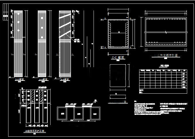
Main application fields Transportation engineering Slope landslide treatment along highways and railways (such as cutting landslides on mountain roads and embankment landslides on railways), especially suitable for scenarios with large landslide thrust where the pile body needs to span deep gullies or complex terrain. Landslide prevention and treatment near tunnel portals and bridge abutments, to prevent landslides from causing structural instability. Water conservancy and hydropower engineering Treatment of reservoir bank slopes and abutment landslides (such as stability reinforcement of dam slopes for earth dams and rockfill dams), to prevent dam failure or reduction of reservoir capacity caused by landslides. Treatment of canal slope landslides, to ensure the safe operation of water conveyance projects. Mining engineering Landslide prevention and treatment for open-pit mine slopes and tailings dam bodies, to avoid safety production accidents caused by landslides (such as sliding of slag accumulation bodies burying working faces). Building and municipal engineering Slope reinforcement for building sites in mountainous areas (such as landslide treatment around basements of high-rise buildings), to prevent building settlement or cracking caused by landslides. Landslide treatment for urban road slopes, park hills, etc., to ensure public safety. Geological disaster prevention and control engineering Emergency treatment or permanent reinforcement of natural landslides (such as large rock landslides and soil landslides), especially suitable for scenarios with large landslide body thickness (>10m) and strong thrust. Mode of action Brief description of anti-slide pile construction Pile hole excavation Rock stratum or hard soil layer: mechanical drilling (such as rotary drilling rig, percussion drill) is adopted, with the borehole diameter slightly larger than the designed pile body diameter (usually 50-100mm larger), to ensure the integrity of the pile wall. Soft soil layer or easily collapsing stratum: manual excavation is adopted, and concrete retaining walls are poured immediately after every 0.5-1m of excavation (retaining wall thickness 100-200mm) to prevent hole wall collapse; if groundwater is encountered, excavation must be carried out while draining water. The excavation method is selected according to geological conditions: The pile hole depth must reach the stable stratum required by the design (the depth embedded in the non-sliding body is usually 1/3-1/5 of the pile length), and the thickness of loose soil at the bottom of the hole shall be ≤100mm. Fabrication and installation of reinforcement cage The reinforcement cage is tied according to the design drawings; the main reinforcement is connected by welding or mechanical connection (the stagger distance of joints shall be ≥35d, where d is the diameter of the main reinforcement), the stirrups are fully welded and fixed to the main reinforcement, and anchor cable ducts are reserved (usually PVC pipes, with position deviation ≤20mm). The reinforcement cage is lifted at two points during hoisting to avoid deformation; after being installed in place, it is fixed to the hole wall to ensure the thickness of the protective layer (usually ≥50mm). Concrete pouring and curing Concrete is poured by the tremie method (to prevent segregation), with the slump controlled at 180-220mm, and vibrated in layers (each layer thickness ≤500mm) until the designed elevation of the pile top is reached. After pouring, it is covered for moisture retention, with a curing period of ≥14 days; subsequent anchor cable construction may proceed only after the concrete strength reaches more than 70% of the design value. Brief description of prestressed anchor cable construction Anchor cable hole drilling After the concrete strength of the pile body reaches the standard, an anchor cable drilling rig is used to drill at the design angle (usually 15°-30°); the borehole diameter is determined according to the anchor cable specifications (such as 150-200mm), and the hole depth must exceed the length of the anchor cable anchorage section by more than 500mm. Slag is removed promptly during drilling; if broken rock strata or water inflow are encountered, simultaneous casing drilling or grouting for wall consolidation may be adopted. Fabrication and installation of anchor cables Anchor cables are usually composed of multiple high-strength steel strands (such as 1860MPa grade), cut to the design length (reserving 1.5-2m for the tensioning section), with a spacer support set every 1-1.5m to ensure the steel strands are arranged in parallel. The steel strands in the anchorage section need to be derusted and sleeved with corrugated pipes (to prevent bonding with cement during grouting); the free section is coated with anti-corrosion grease and sleeved with a PE pipe, with both ends sealed. During installation, the anchor cable is slowly placed into the hole to avoid twisting or scratching, ensuring that the anchorage section is located in the stable stratum. Grouting of the anchorage section A high-pressure grouting pump is used to inject cement slurry (water-cement ratio 0.4-0.5); the grouting pipe is inserted to 500mm from the bottom of the hole and slowly withdrawn while grouting, ensuring the slurry fills the gap between the hole wall and the anchor cable, with the grouting pressure controlled at 0.5-1.0MPa. If the slurry return at the hole opening is insufficient after grouting, supplementary grouting is required 1-2 times; the next step may proceed only after the slurry initially sets (usually 24 hours). Determination of anchor cable tension Relevant formulas Bending moment M₀ and shear force Q₀ of the pile at point O at the top of the pile anchorage section: M₀ = M - Σ(Rj×Lj); Q₀ = Q - ΣRj. In the formulas, M and Q are respectively the bending moment and shear force acting on point O of the pile due to landslide thrust or rock and soil pressure; Rj is the tension of the j-th row of anchor cables; Lj is the distance from the anchor point of the j-th row of anchor cables to point O. Relationship between anchor cable elongation and pile displacement: According to the principle of displacement and deformation coordination, the elongation δi of each anchor cable is equal to the displacement fi of the pile at the point where the anchor cable is located, i.e., δi = fi. Where δi = li×(Ri - Rio) / (Eg×As), li and As are respectively the length of the free section of the anchor cable and the cross-sectional area of each bundle of anchor cable, Eg is the elastic modulus of the anchor cable, N is the number of bundles of anchor cable per hole, and Rio is the initial prestress of the i-th anchor cable. fi = X₀ + θ₀×Li + iq - Σ(ij), where X₀ and θ₀ are respectively the displacement and rotation angle of the pile at point O at the top of the pile anchorage section, and iq and ij are respectively the displacements of the pile at point i caused by the landslide thrust (or rock and soil pressure) and the anchor cable tension Rj. Calculation of ij: When j>i, ij = Lj³ / (6×EI)×(2 - 3×(Li / Lj) + (Li / Lj)³); when j≤i, ij = Lj² / (6×EI)×(2 - 3×(Lj / Li) + (Lj / Li)³), where E and I are respectively the elastic modulus and cross-sectional moment of inertia of the pile. Calculation of X₀ and θ₀: X₀ = Q₀×(1 / (3×EI)) + M₀×(2 / (2×EI)); θ₀ = Q₀×(2 / (3×EI)) + M₀×(3 / (2×EI)). Let Ai = 1 / (3×EI) + 2 / (2×EI)×Li, Bi = 2 / (2×EI) + 3 / (EI)×Li, then X₀ + θ₀×Li = Ai×Q₀ + Bi×M₀. Solving anchor cable tension by linear equations: Substituting and rearranging the above relevant formulas yields Σ(ij×Rj) + i×Ri = Ci; the tension Rj of each row of anchor cables can be determined through the linear equations, Rj = Dj / D, where D is the coefficient determinant, and Dj is the determinant obtained by replacing the elements in the j-th column of D with Ci. Calculation of internal forces of the anti-slide pile body Internal forces of the pile body in the non-anchorage section OA Shear force: When y = L - Li, take K = n + 1 - i (i = 1, 2, …, n), Q -y = Q (y) - Σ(Rn + 2 - j); when L - Li - 1 > y ≥ L - Li, take K = n + 2 - i (i = 1, 2, …, n + 1), Qy = Q (y) - Σ(Rn + 2 - j). Bending moment: My = M (y) - Σ(Rn + 1 - j)×(y - (L - Ln + 1 - j)). In the formulas, Qy and My are the shear force and bending moment of the pile body, Q (y) and M (y) are the shear force and bending moment acting on the pile due only to rock and soil pressure, and K is the number of anchor cable support points counted from the pile top downward. Calculation of internal forces of the pile body in the anchorage section: The internal forces of the pile body in the anchorage section are calculated in accordance with ordinary anti-slide piles, using the multi-segmentcoefficient of subgrade reactionmethod; the pile body in the anchorage section is divided into several small segments, the coefficient of subgrade reaction of each small segment is regarded as rectangularly distributed, the pile deformation coefficient is introduced, and calculation is performed according to the "K" method or the "m" method.

"New Recruit" Joins the Ranks! Zoomlion Fire Trucks Help Strengthen Summer Safety Defenses
下一篇Innovative Technology | New Alliance Patent: Clamping-Press Static Anchor Pile Technology

2026-10-18 0 0

2026-10-18 0 0

2026-10-17 0 0

2026-09-23 10598 0
Lize City Air Terminal Underground Main Structure Nearing Completion: Maximum Transfer Walk Under 4 Minutes After Operation
Anti-seepage Curtain for Main Lock Pit of CSCEC Port Shenqiu Double-Line Lock Project Completed on Schedule
All Pile Foundations Completed on Quanzhou Baiqi Channel

Hainan Upgrades Housing and Municipal Infrastructure
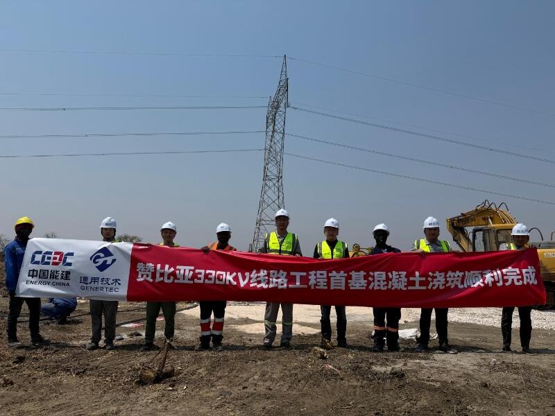
First Foundation Concrete Pour Successfully Completed for Zambia Kafue West–Muzuma 330kV Transmission Line EPC Project
Hot News

评论 (0)