1. Contents of foundation pile calculation
◆ Calculation of internal forces in pile shaft section and section verification
◆ Pile length calculation
2. Calculation of internal forces in pile shaft section and section verification
The calculation contents and methods are the same as those for pier columns:
Calculate the maximum bending moment of the pile shaft, which is generally about 3 m below the ground surface. Extract the internal forces at this calculated section for reinforcement calculation and section verification.
The m-method is adopted for all cases (see Appendix P of the Code for Design of Ground Bases and Foundations of Highway Bridges and Culverts).


For eccentrically loaded compression members, the calculation is the same as that for pier columns.
For the calculated length of the pile, the new code does not specify; refer to the 1985 ground base code:


The soil spring in a finite element program may also be used to simulate pile-soil interaction; for details, refer to the book Bridge Design and Calculation and the references therein.

Soil spring stiffness: K=b1*S*m*y
b1 — calculated width
S — pile element length
y — element depth

Pile foundation reinforcement
Reinforce according to the calculation results, with reference to the Guiding Opinions on Pile Foundation Design of the High-grade Highway Command:
Friction pile:
1. For the first batch of cut-off main reinforcement, the length extending underground is L, calculated as L1=4/α (α is the deformation coefficient of the foundation in soil).
2. The lowest section is a plain concrete segment, with a maximum length not exceeding 8 times the pile diameter.
3. Thickness of the sediment layer at the pile foundation:

Rock-socketed pile: the pile foundation reinforcement runs the full length.
Sediment layer thickness:

Pile foundation testing:
For pile length <50 m, the low-strain method may be used for testing.
For pile length ≥50 m, the sonic transmission dynamic test method is used, with sonic logging tubes embedded:
Pile diameter d<180 cm: 3 tubes
Pile diameter d≥180 cm: 4 tubes

Note: for construction convenience, extend the main reinforcement to fix the sonic logging tubes.
3. Pile length calculation
Calculation of reaction at pile top (JTG D63-2020 Code for Design of Ground Bases and Foundations of Highway Bridges and Culverts)

Note: the load factor is 1.0, not 1.2 or 1.4, and the impact factor of 0.3 is included.
Note:
1. Consider negative skin friction.

2. Consider scour, riverbed changes, etc.
Friction pile


1. The difference between the pile self-weight and the equivalent soil weight is generally taken as 25-18=7 kN/m3.
2. The bearing stratum is mostly sandy soil, so buoyancy is fully considered, γ2=8 kN/m3. For saturated cohesive soil with IL<0, buoyancy is not considered; for IL>1, buoyancy is considered. For values between 0 and 1, the unfavorable state is considered.
3. If detailed soil data are unavailable, conservative values may be adopted.
Rock-socketed pile


The clause explanation specifies the lithology of the bearing stratum for rock-socketed piles:

1. Moderately weathered rock is calculated as rock-socketed pile; strongly weathered rock is still calculated as friction pile.
2. Uniaxial saturated compressive strength:

Rock-socketing depth:

1. The rock-socketing depth is calculated according to Clause 5.3.5 of the code.
2. If the pile is relatively long and the bending moment at the pile end is very small, considering unfavorable factors such as rock stratum variation, weathering differences, and fracture development, a rock-socketing depth of 1.5~2d may be considered.
Strengthen the distribution of boreholes to ensure accurate and reliable geological data. Clause 6.3.3 of the Code for Geological Survey of Highway Engineering (JTJ064-98):

3. Example of pile length calculation
For an interchange bridge at a junction, the rock stratum distribution varies greatly, and the moderately weathered layer lies 5~15 m below the ground line.


Borehole layout: boreholes are arranged at alternate piers, and they are required to penetrate at least 5 m into the moderately weathered layer.
The designed pile lengths range from 10 to 22 m, with rock socketing >3 m, and adjustments were made on site according to the borehole conditions.
Construction methods: percussion drilling, hand-dug caissons, etc.


Safeguarding the Red Roots, Setting an Example of 'Pioneering' | Jingjiu Participates in Thematic Study on the Spirit of General Secretary Xi Jinping's Important Speech During His Inspection of Zhejiang
下一篇Xiang Wenbo: BRICS Countries Are a Historic Opportunity Not to Be Missed for Sany's Development!

2024-09-29 13335 0

2024-09-20 13336 0

2024-09-20 13180 0

2024-09-19 12457 0

Lize City Air Terminal Underground Main Structure Nearing Completion: Maximum Transfer Walk Under 4 Minutes After Operation

Anti-seepage Curtain for Main Lock Pit of CSCEC Port Shenqiu Double-Line Lock Project Completed on Schedule

All Pile Foundations Completed on Quanzhou Baiqi Channel

Hainan Upgrades Housing and Municipal Infrastructure
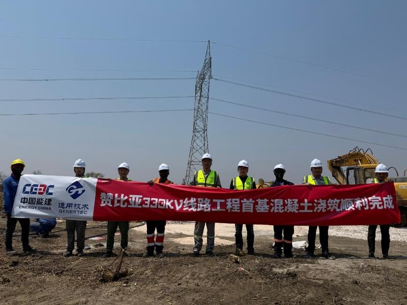
First Foundation Concrete Pour Successfully Completed for Zambia Kafue West–Muzuma 330kV Transmission Line EPC Project
Hot News

评论 (0)