(1) Purpose and methods of foundation pit dewatering
◆ Solve the problem of confined water inrush
◆ Solve the problems of base and slope stability
◆ Improve earthwork excavation efficiency and facilitate in-pit construction operations
◆ Minimize environmental impact

(2) Current status of groundwater control
◆ Owners, designers, constructors, and supervisors all lack hydrogeological or related technical personnel, and their understanding and comprehension of groundwater are not thorough enough.
◆ The retaining structure design is unreasonable, or water is blocked as soon as it is encountered, causing excessive waste, or it is considered only from the stress aspect, which is insufficient.
◆ The construction party relies too much on experience, or does not pay enough attention; differences in hydrogeological conditions are not considered.
◆ The management party cannot grasp the key points
For example: a foundation pit project at a certain center in Nanjing, with an area of about 100,000 m2 and an excavation depth of 14.70~16.00 m. The retaining structure is a diaphragm wall, 62 m deep, penetrating into moderately weathered mudstone. Serious waste.

For the Jiangnan shaft of the Wei San Road river-crossing tunnel in Nanjing, in order to cut off the hydraulic connection between the inside and outside of the pit in the lower confined aquifer, the designer made the diaphragm wall penetrate into the bedrock weathered layer. Construction of one diaphragm wall panel required 7 days. As a result, the confined water was not cut off, and because the joints of the diaphragm wall were not properly treated, the confined water entered the foundation pit along the diaphragm wall joints, causing piping.


Many accidents appear accidental but are actually inevitable. 
(3) Types of foundation pit engineering dewatering
According to the geological characteristics of the foundation pit project, the insertion depth of the retaining structure, and the location of dewatering wells, foundation pit dewatering can be divided into the following 4 types:
1. Type 1 foundation pit engineering dewatering — dewatering of a foundation pit where the watertight curtain penetrates into the aquiclude floor of the dewatering aquifer
2. Type 2 foundation pit engineering dewatering — dewatering of a foundation pit where the watertight curtain does not penetrate into the dewatering aquifer
3. Type 3 foundation pit engineering dewatering — dewatering of a foundation pit where the watertight curtain penetrates into the dewatering aquifer
4. Type 4 foundation pit engineering dewatering — dewatering of a foundation pit without a watertight curtain
Type 1 foundation pit engineering dewatering — dewatering of a foundation pit where the watertight curtain penetrates into the aquiclude floor of the dewatering aquifer
Because the watertight curtain penetrates into the aquiclude floor of the dewatering aquifer, it blocks the hydraulic connection between the aquifers inside and outside the pit. This is a fully closed type of dewatering, so the in-pit dewatering method is adopted, that is, dewatering wells are arranged inside the foundation pit. If the target aquifer for dewatering is an unconfined aquifer, it is dewatering by drainage; if the target aquifer for dewatering is a confined aquifer, then the early stage of dewatering is pressure reduction and the later stage is drainage. Since groundwater is mainly pumped from inside the pit, the dewatering objective is easily achieved, the dewatering effect is obvious, and the dewatering influence range is small, with little impact on the surrounding environment.

Groundwater flow characteristics: Because the watertight curtain blocks water, there is no hydraulic connection between the groundwater inside and outside the foundation pit. During in-pit dewatering, the groundwater level outside the foundation pit is not affected. In actual projects, the retaining structure cannot be completely watertight.
Type 2 foundation pit engineering dewatering — dewatering of a foundation pit where the watertight curtain does not penetrate into the dewatering aquifer
This is fundamentally different from Type 1 foundation pit engineering dewatering. Type 1 engineering dewatering is a kind of drainage dewatering, that is, draining the groundwater in the water-bearing soil body enclosed by the foundation pit watertight curtain and the aquiclude floor; Type 2 engineering dewatering is to lower the water level in the confined aquifer below the excavation surface of the foundation pit to a certain extent, preventing uplift or water inrush at the pit bottom and meeting the safety requirements of foundation pit excavation. It is a typical decompression dewatering.

The watertight curtain is located above the target aquifer for dewatering and does not separate the confined aquifer inside and outside the foundation pit. The effect of dewatering outside the pit is basically the same as that of dewatering inside the pit. Therefore, for the convenience of in-pit construction, dewatering wells can usually be arranged outside the foundation pit.
The influence range of this type of engineering dewatering is relatively large, but the drawdown cone is gentle, and the ground settlement caused by pumping is uniform settlement.
Type 3 foundation pit engineering dewatering — dewatering of a foundation pit where the watertight curtain penetrates into the dewatering aquifer
Because the underground retaining structure or watertight curtain penetrates into the dewatering aquifer, it partially cuts off the hydraulic connection between the inside and outside of the foundation pit. Groundwater flow is blocked, and the seepage boundary becomes very complex. Groundwater presents a three-dimensional flow state, and dewatering design often requires analysis and calculation with the help of three-dimensional seepage calculation software.

For areas with large aquifer thickness and complex surrounding environment, this method is often used for groundwater level control. Due to the water-blocking effect of seepage around the retaining structure, during in-pit dewatering, a large water level difference often occurs between the inside and outside of the foundation pit, and piping must be prevented.
Type 4 foundation pit engineering dewatering — dewatering of a foundation pit without a watertight curtain
There is usually no water-stop curtain around the foundation pit, or the watertight curtain is incomplete, and the obstruction effect on groundwater flow is not obvious. The dewatering influence range is relatively large. Therefore, the surrounding environmental conditions are required to be good, with no important pipelines (especially gas pipelines, water supply and drainage pipes, etc.) and no key protected buildings (structures). In dewatering design, the main purpose is to lower the water level, and the impact on the environment is not considered.

According to the relative position of dewatering wells and the foundation pit, it can also be divided into outside-pit dewatering and in-pit dewatering

(4) Foundation pit engineering dewatering design
Condition analysis

Relevant calculation formulas
(1) Calculation formula for stability against inrush at the pit bottom under the action of confined water

(2) Calculation formula for total water inflow


(3) Calculation formula for water yield of a single well

(4) Calculation formula for the number of dewatering wells

(5) Calculation formula for stratum deformation caused by dewatering

(6) Dewatering design under complex conditions — numerical method
◆ Visual MODFLOW is currently the most popular internationally and unanimously recognized standard visual professional software system for three-dimensional groundwater flow and solute transport simulation and evaluation. This system was developed by Waterloo Hydrogeologic in Canada on the basis of the original MODFLOW software using modern visualization technology, and was first released internationally. This software package consists of three major parts: Modflow (water flow evaluation), Modpath (planar and cross-sectional streamline tracing analysis), and MT 3D (solute transport evaluation), and has powerful graphical visual interface functions. The innovatively designed menu structure allows users to very easily directly delineate model areas and subdivide calculation units on the computer, and conveniently assign values directly to each subdivided unit and boundary condition on the machine, achieving true human-computer dialogue.
◆ The interface design includes three major modules that are interrelated but quite independent, namely the input module, the run module, and the output module.
◆ It can simulate groundwater flow conditions under different complex conditions and can effectively solve the impact of water-stop curtains, various boundaries, and other factors on groundwater flow.

(5) Foundation pit engineering dewatering management
Management and control at three stages
◆ Design stage — technically feasible, economically reasonable, safe and reliable technical scheme
◆ Construction stage — well completion quality control, pumping tests, trial dewatering, etc. (dynamic management)
Dewatering well construction stage: verify the selection of well completion technology, verify the water yield of a single well, and adjust the dewatering scheme. After the dewatering wells are completed: before excavation, conduct a productive verification pumping test to verify whether the groundwater can be lowered to the design water level and to verify the water-stop effect of the retaining structure.
◆ Operation stage — water level monitoring (key point), protection of dewatering wells.
(1) Well completion quality — water yield of a single well
The measured water yield when the water level in the tube well reaches the design drawdown should not be less than the design water yield of the tube well, and the water yields of the wells should not differ greatly (uniform).
Generally, in the absence of curtain influence, the water yield of a single well is:
Silty sand 2~5 m3/h
Fine sand 8~15 m3/h
Fine silty sand 20~100 m3/h.

(2) Control of sand content in discharged water
The Technical Code for Dewatering Engineering of Building and Municipal Engineering requires:
When all dewatering wells are running, the sand content of the pumped water shall comply with the following provisions:
Coarse sand content shall be less than 1/50,000;
Medium sand content shall be less than 1/20,000;
Fine sand content shall be less than 1/10,000;
Water supply wells are required to be less than 1/200,000.
(3) Dewatering well structure
◆ Pipe diameter design — Ф273 mm, Ф325 mm, determined by the water yield of a single well and the outer diameter of the pump; the pipe diameter does not determine the water volume
◆ Pipe material selection — steel pipe, sand-free concrete pipe, PVC pipe
◆ Filter material requirements — gravel, melon-seed stone, medium-coarse sand, selected according to the stratum particle size
(6) Groundwater recharge technology
Working principle of recharge
A row of recharge wells (injection wells) is set between the pumping wells and the protected buildings (structures), and while pumping, water is injected underground through the recharge wells. Thus, near the original buildings, on the one hand, the groundwater level drops due to groundwater extraction; on the other hand, the water injection through the recharge wells causes the groundwater level to rise. The combined effect keeps the actual groundwater level around the foundation pit for the protected buildings (structures) unchanged or within the allowable range. This is the most economical and practical measure for controlling ground settlement. Recharge technology is mostly used in soil layers with good permeability. The recharge volume of recharge wells depends on the permeability of the stratum, the quality of the recharge wells, and the recharge water source.


Current status of recharge — most cannot meet requirements

◆ Pressurized recharge — theoretically feasible, but difficult in actual construction and easy to clog filter pipes

◆ Water quality treatment (iron and manganese removal) — not practical
◆ Water quality is improved to some extent, but the treated water volume is limited and cannot meet the recharge volume requirement, and a large amount of air bubbles is mixed in, affecting the recharge effect.


Atmospheric pressure, raw water recharge — a process worth promoting
Recharge effect verification — observation hole water level and ground settlement monitoring

(7) Groundwater control technology for shield launching and receiving in water-rich strata
◆ In water-rich strata, groundwater is the greatest risk source during shield launching and receiving.
◆ In order to prevent inrush, piping, flowing sand, and other phenomena when the shield enters and exits the tunnel, measures such as reinforcement, freezing method, and dewatering are usually adopted, and even the three are used simultaneously.
◆ When the surrounding environment permits, reinforcement + dewatering is the most economical and safe means

◆ Adding a water-stop curtain (plain wall, triple-axis mixing pile) outside the end reinforcement area, with depth penetrating into the lower weakly permeable layer or into the aquifer to a certain depth, can produce a disturbing and water-blocking effect. Then a small number of dewatering wells arranged inside the curtain can control the water level at a safe level, while also reducing the impact on the surrounding environment and increasing the safety of shield launching and receiving.

(8) Underground treatment of several special strata
Granite weathered layer
Mainly refers to the completely weathered layer. In a saturated state, it is mainly composed of three substances: mud (weathered feldspar), sand (quartz particles), and water. In a natural state, excavation shows a flow state, grouting is difficult (saturated), the permeability coefficient is 0.1~0.5 m/d, and dewatering is difficult. However, after effective dewatering, the strength of the stratum increases. It is widely distributed in Guangdong and Fujian in southern China. Whether for open-cut foundation pits or mined tunnels, if dewatering technology can be effectively adopted, costs can be greatly saved and safety improved.

Dewatering of muddy soil strata
Dewatering of muddy soil strata is the most difficult. The soil moisture content is generally 40%~70%, and soil particles wrap water like willow catkins. It belongs to weakly bound water, and direct gravity drainage has a poor effect. Usually, muddy soil strata contain a certain amount of silty soil interlayers, and ordinary tube wells can be used for direct dewatering, or combined with vacuum dewatering, with a long pre-dewatering time; if it is pure muddy soil, the vacuum dewatering effect is also poor, and plastic drainage boards + surcharge preloading + vacuum dewatering can be adopted.
Karst strata
Karst water is mainly blocked. It is best not to adopt dewatering measures. First, the water volume is too large; second, it may also trigger karst collapse.

1.2 Billion! Sichuan Building Construction Bidding
下一篇Meet in Tianjin! XCMG Energy Equipment Invites You to the 25th China Mining Conference and Exhibition!

2024-09-29 13335 0

2024-09-20 13336 0

2024-09-20 13180 0

2024-09-19 12457 0

Lize City Air Terminal Underground Main Structure Nearing Completion: Maximum Transfer Walk Under 4 Minutes After Operation

Anti-seepage Curtain for Main Lock Pit of CSCEC Port Shenqiu Double-Line Lock Project Completed on Schedule

All Pile Foundations Completed on Quanzhou Baiqi Channel

Hainan Upgrades Housing and Municipal Infrastructure
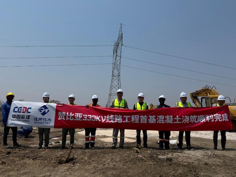
First Foundation Concrete Pour Successfully Completed for Zambia Kafue West–Muzuma 330kV Transmission Line EPC Project
Hot News

评论 (0)