China Construction Eighth Engineering Division Corp., Ltd. Zhang Kuan
China Construction Eighth Engineering Division Third Construction Co., Ltd. Liu Bohu
Preface:
In response to different geological conditions and different building load situations, we dare to innovate, make full use of bearing strata at different depths with different bearing capacities in the geological structure, and, in accordance with building load requirements, flexibly adopt piles of different lengths and types as the pile foundation. This not only gives full play to the advantages and characteristics of different piles, but also greatly reduces costs.
Abstract
Through the successful application of the first combined pile foundation cap in China in which bored cast-in-place piles and prestressed pipe piles are used within the same pile cap, this project provides more ideas for the selection of pile foundation types when the building structure is complex, the loads are uneven, the foundation bearing capacity is uneven, and the differences between uplift piles and compressive piles are relatively large.
1. Engineering geological overview
A certain confidential scientific research project—the main building of the administrative information center of a certain university has 12 stories and 1 basement (story height 4 m). The geological characteristics are those of a relatively typical coastal plain and tidal flat. The upper part of the geological structure consists of soft, highly compressible clay and silt soil. At a buried depth of about 36 m there are two layers of medium-dense round gravel; the upper round gravel layer is about 2.5 m thick, and the lower round gravel layer is about 2.0 m thick. Between the upper and lower round gravel layers is a highly compressible clay layer about 1.5 m thick in a plastic state. Below that is medium-dense highly compressible clay, and down to a depth of 70 m is clay interbedded with medium-fine sand, of medium compressibility, with a layer thickness of about 10 m. Among these, at a buried depth of about 36 m there are two layers of medium-dense round gravel (the bearing stratum of the shorter prestressed pipe piles optimized for this project); the upper round gravel layer is about 2.5 m thick, and the lower round gravel layer is about 2.0 m thick (between the upper and lower round gravel layers is a highly compressible clay layer about 1.5 m thick in a plastic state). Extending further downward is medium-dense highly compressible clay, and down to a depth of 70 m is clay interbedded with medium-fine sand, of medium compressibility, with a layer thickness of about 10 m (the bearing stratum of the longer bored cast-in-place piles optimized for this project).
2. Design overview
2.1 Introduction
Article 3.2.3.4 of the Technical Code for Building Pile Foundations JGJ94—94 stipulates: "Different types of piles should be avoided within the same structural unit." After successful practical verification in this project, the new edition of the Technical Code for Building Pile Foundations JGJ94—2008 accordingly removed this provision.
2.2 Combination form of the pile foundation
The main building foundation of this project consists of two pile types, bored cast-in-place piles and prestressed pipe piles, which are distributed geometrically symmetrically within the same pile cap. This combined pile foundation form is the first of its kind in China and internationally. Specifically, the main building uses 132 Ф700 and 12 Ф600 concrete bored cast-in-place piles, all 68 m long (with the pile top buried at a depth of 2 m) (construction is based primarily on the pile end penetrating 30–50 cm into the medium-dense clay interbedded with medium-fine sand bearing stratum); in addition, it includes 104 PTC-A500 prestressed concrete pipe piles 34 m long. Therefore, the foundation form is a combined pile foundation of 34 m long prestressed pipe piles and 68 m long bored cast-in-place piles. The bearing stratum of the concrete bored cast-in-place piles is the clay layer interbedded with medium-fine sand at a buried depth of about 70 m; the bearing stratum of the prestressed concrete pipe piles is the upper round gravel layer of the two medium-dense round gravel layers at a buried depth of about 36 m. Moreover, the two types of piles are distributed within the same pile cap in a certain geometrically symmetric manner, forming composite pile caps of 4 piles, 5 piles, 6 piles, and 7 piles. The layout of pile positions within pile caps with various pile arrangements is shown in Figure 2-1 below.

(a) Seven-pile cap (b) Four (five)-pile cap (c) Six-pile cap

Figure 2-1 Layout and section schematic of different piles within the same pile cap
3. Engineering characteristics and difficulties
(1) The settlement difference and load-bearing difference of "combined piles of different types" are related to the distribution of loads according to their respective design bearing capacities. That is to say, when "combined piles of different types" act together under the same load with different bearing capacities, how to distribute the load in proportion to their bearing capacity requires solving the problems of secondary, tertiary, or multiple redistribution and rebalancing of loads by adjusting the settlement and deformation of each type of pile.
(2) In construction, solving the technology for constructing the two combined pile types is by no means a simple addition of the two technologies. It is necessary not only to consider the respective characteristics and unique construction technologies of the two pile types, but also to consider the mutual influence, mutual interference, and even damage between the two different piles, and to resolve and eliminate these factors one by one. This requires that the scheme prediction be very rigorous, scientific, and comprehensive.
(3) According to the building form and structural characteristics, arrange more reasonably the relative positions of different pile types within the same pile cap in terms of safety, reliability, practicality, rationality, scientificity, and economy.
4. Construction technology and parameter control
Due to the innovation in the design of this project, and in the absence of construction experience and data for combined pile foundations, the construction difficulty was greatly increased. However, in the construction process, in the spirit of advancing despite difficulties and strictly innovating, numerous difficulties were overcome, a series of technical problems were solved, and the following construction technology was formulated.
4.1 Construction sequence of the two pile types
Because there are two types of piles within the same pile cap, and the construction sequence of the two pile types affects each other: if the prestressed pipe piles are constructed first, the disturbance of the soil layer is unfavorable for the hole formation of the bored cast-in-place piles. The stress generated by the pipe piles on the soil layer will be released during hole formation of the bored piles, which will reduce the friction bearing capacity of both pile types (both pile types are mainly friction piles). In addition, during hole formation of the later-constructed bored piles, diameter shrinkage and hole collapse are likely to occur, causing the bearing stratum of the prestressed pipe piles located in the shallow bearing stratum to lose friction due to hole collapse, or even locally generate negative friction. If the bored cast-in-place piles are constructed first, there are also defects such as hole collapse causing loss of the bearing stratum of the prestressed pipe piles, but during construction of bored cast-in-place piles, hole collapse can be completely avoided through mud slurry wall protection during hole formation. After repeated analysis and demonstration, the construction sequence of "long first, short later; deep first, shallow later; non-displacement piles first, displacement piles later" was finally determined, that is, construct the bored cast-in-place piles first and then the prestressed pipe piles.
4.2 Influence of the construction sequence of the two pile types and measures
If the bored piles are constructed first and hole collapse causes some loss of the bearing stratum of the pipe piles, through causal analysis, the causes of hole collapse are found, and through analysis and discussion, measures are formulated as shown in Table 4-1: Measures to reduce the mutual influence of construction of the two pile types.
Table 4-1 Measures to reduce the mutual influence of construction of the two pile types


4.3 Connection timing of the two pile types
As a combined pile, the higher the strength of the pile body concrete of the bored cast-in-place piles, the smaller the damage to the bored cast-in-place piles caused by the stress and vibration generated by soil squeezing during construction of the prestressed pipe piles. In order to accurately measure and control the concrete strength of the bored piles, multiple groups of test blocks cured under the same conditions were retained during construction as staged testing of the concrete strength of the bored pile body, thereby determining the appropriate time for construction of the prestressed pipe piles. As the first case in China of combined piles within the same pile cap, in order to ensure quality and protect the previously constructed bored cast-in-place piles, this project deliberately waited until the concrete strength of the bored piles reached 100% (28 days after pouring of the bored piles) before starting construction of the prestressed pipe piles. During construction, to ensure progress, the concrete strength of the bored cast-in-place pile body was tested by sections, and construction of the prestressed pipe piles was inserted in stages, connected in sequence in a flow-line manner.
4.4 Reducing the influence of the soil-squeezing effect
(1) How to reduce the flow direction of pipe piles
The soil-squeezing effect on bored piles is minimized in the soil-squeezing direction. Reasonable flow-line construction and skip driving are adopted, that is, within the same pile cap or a small section, and even in the entire construction flow-line plan, the flow is carried out "from inside to outside," "from point to area," and "from area to surface." When the pile spacing is small (below 4 times the pile diameter) and the number of piles is relatively dense, skip driving is adopted. The site is required to be hardened to ensure convenient machine movement and reduce local uneven loading of the soil by the pile machine. The flow direction must be ensured, and flow requirements must not be ignored because of arbitrary machine movement due to soft site conditions and inconvenient machine movement.
(2) Selection of hammer type for pipe piles and quality protection of combined piles
The hammer type selected during construction of prestressed pipe piles must be consistent with the construction technology of the combined piles. The hammer weight must not be too large, so as to avoid excessive vibration energy and excessively fast soil-squeezing rate, which would affect the concrete quality of the bored cast-in-place pile body and easily break the pipe pile heads, and would also affect the quality of pipe pile splicing of the prestressed pipe piles. However, a hammer that is too small is also unfavorable for sinking the prestressed pipe piles and easily causes fatigue damage to the prestressed pipe piles. After analyzing the geological characteristics and the design strength of the concrete of the bored cast-in-place pile body, a 2.5-ton pile hammer was selected for this project, which was relatively appropriate, and construction proceeded relatively smoothly.
(3) Determination of the primary and secondary "double control" indicators for pipe piles and their relationship with adjustment of settlement difference
"Double control" refers to the control standards of "for friction piles, the stopping standard is mainly based on elevation, supplemented by penetration" and "for end-bearing piles, the stopping standard is mainly based on penetration, supplemented by elevation." The settlement of friction piles is slightly greater than that of end-bearing piles. In this project, the contour lines of the geological distribution of the gravel layer vary greatly, and the density and thickness of the gravel layer are uneven. During construction, the "double control" operating standards were determined according to different strata: when the thickness and density of the round gravel layer are relatively large, the penetration increases abruptly and vibration is severe when the pipe pile reaches the bearing stratum, so hammering should be stopped immediately to avoid breaking the pipe pile and to avoid vibration effects on the bored pile concrete; when the thickness and density of the round gravel layer are relatively small, the penetration change is not obvious and vibration is slight, so pile driving should continue to the design penetration, and the reduced pile top elevation can be made up by pile splicing after excavation; when between the above two cases, scale lines should be marked on the pile body, and a level should be used to measure and control the final penetration to determine the stopping standard.
4.5 Protection of the two different pile types during deep foundation pit excavation
The excavation depth of this project is more than 3 m, and within the excavation depth is a soft silty soil layer with very poor self-stability, where landslides and collapse are very likely to occur on the excavation section. Pipe piles with relatively poor overturning resistance are very likely to suffer shear failure and pile breakage, while bored piles have relatively good shear resistance. Therefore, excavation should be carried out in layers, and temporary rest sections must not be left at pipe pile locations. If piles are selected as slope protection support points, pipe piles must not be used; bored piles may appropriately be used as support points.
5. Significance of use and economic effects
Pile layout characteristics:The main building pile foundation uses bored piles of diameter ф700/600 and length 68 m and prestressed pipe piles of diameter ф500 and length 36 m, among which the bored piles are arranged along the longitudinal axis direction and the pipe piles along the transverse axis direction.
This design makes full use of the two "deep and shallow" "bearing strata" and adopts "two combined piles of long and short lengths," thereby greatly reducing costs while meeting engineering requirements. This design concept provides good inspiration and a precedent for reducing costs under geological conditions containing sand interbeds and gravel strata.
According to on-site static load tests, the design ultimate bearing capacity of the pipe piles is 2000 kN, and the test load reached 2217.6 kN; the design ultimate bearing capacity of the bored piles is 4500 kN, and the test load was greater than 4500 kN. The design ultimate bearing capacity of the composite 4-pile cap of 2 bored piles and 2 pipe piles is 13500 kN, and the test load was greater than 14010 kN. All meet or exceed the original design ultimate bearing capacity requirements and satisfy the code settlement provisions. The two types of piles each have their own load-bearing characteristics: the design ultimate bearing capacity of the pipe piles is 2000 kN, and the test load reached 2217.6 kN; the design ultimate bearing capacity of the bored piles is 4500 kN, and the test load was greater than 4500 kN. In terms of bearing capacity, bored piles account for 70% and pipe piles for 30%.
Moreover, in follow-up research and tracking inspections for many years after completion of the project, the stress-strain testing, the quality of the two pile types, and settlement all achieved the expected results.
As shown in Figure 5-1 below:

Figure 5-1 Static load test results of combined piles
In various follow-up stress-strain tests for many years after completion of the project, the quality and settlement of the two pile types all achieved the expected results. The design parameters of the combined piles and the construction technology of the new process were summarized.
6. Conclusion
6.1 Meeting structural requirements and bearing capacity requirements
According to static load tests, the design ultimate bearing capacity of the pipe piles is 2000 kN, and the test load reached 2217.6 kN; the design ultimate bearing capacity of the bored piles is 4500 kN, and the test load was greater than 4500 kN. The design ultimate bearing capacity of the composite 4-pile cap of 2 bored piles and 2 pipe piles is 13500 kN, and the test load was greater than 14010 kN. All meet or exceed the original design ultimate bearing capacity requirements and satisfy the code settlement provisions.
6.2 Substantial cost reduction
The original design of this project was entirely bored piles (including three podium buildings), with a cost of more than 11 million yuan; after using this composite pile foundation for the main building and pipe piles for the podium buildings, the cost was reduced to 4.5 million yuan (including the three podium buildings), a reduction of 6.5 million yuan, or 60%, compared with the initial design. Moreover, this composite pile foundation has become a very effective foundation form for reducing costs while ensuring project quality. This composite pile foundation of piles of different types and different lengths was the first of its kind in China in this project, inspiring new ideas for greatly reducing costs.
This article is excerpted from the Proceedings of the 12th Deep Foundation Engineering Development Forum
Good News Keeps Coming | Jianhua Building Materials Wins Multiple Science and Technology Innovation Honors, Supporting High-Quality Development of the Precast Pile Industry
下一篇Over 1,100 Tons! First Steel Cofferdam for Quxi River Double-Track Extra-Large Bridge on Chongqing-Wanzhou High-Speed Railway Enters Water

2024-09-29 13335 0

2024-09-20 13336 0

2024-09-20 13180 0

2024-09-19 12457 0

Lize City Air Terminal Underground Main Structure Nearing Completion: Maximum Transfer Walk Under 4 Minutes After Operation

Anti-seepage Curtain for Main Lock Pit of CSCEC Port Shenqiu Double-Line Lock Project Completed on Schedule

All Pile Foundations Completed on Quanzhou Baiqi Channel

Hainan Upgrades Housing and Municipal Infrastructure
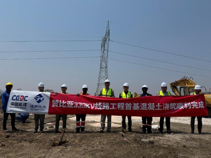
First Foundation Concrete Pour Successfully Completed for Zambia Kafue West–Muzuma 330kV Transmission Line EPC Project
Hot News

评论 (0)