1. What are anti-slide piles?
Anti-slide piles are pile columns that penetrate through the landslide body and extend into the sliding bed to resist the sliding force of the sliding mass and stabilize the slope. They are suitable for shallow and medium-thick landslides and are a primary measure for anti-slide treatment. The use of anti-slide piles involves a small amount of earthwork, requires supporting mechanical equipment for construction, and has a short construction period, making it a widely adopted anti-slide measure.
2. Functions of anti-slide piles
The function of anti-slide piles on a landslide body is to use the resistance (anchoring force) of the pile inserted into the stable stratum below the sliding surface to balance the thrust of the sliding mass and increase its stability. When the landslide body slides downward, it is resisted by the anti-slide pile, causing the sliding mass in front of the pile to reach a stable state. Depending on the thickness of the sliding mass, magnitude of thrust, waterproofing requirements, and construction conditions, wooden piles, steel piles, concrete piles, and reinforced concrete piles are selected. According to general experience, the anchoring depth of anti-slide piles embedded below the ground is one-third of the design pile length in soft rock, one-quarter of the design pile length in hard rock, and one-half of the design pile length in soil sliding beds. When the soil layer slides along the bedrock surface, the anchoring depth may also be 2 to 5 times the pile diameter. The arrangement forms of anti-slide piles include interconnected pile rows, spaced pile rows, pile rows with spacing at the bottom and connection at the top, and spaced anchor piles. The spacing between piles is generally 3 to 5 times the pile diameter, based on the principle of ensuring that the sliding soil mass does not slip out between piles.
II. Construction Process of Anti-Slide Piles
1. Flowchart of Rotary Drilling Pile Construction Process

2. Site Preparation
(1) After the construction platform is filled, the pile positions are determined using the coordinate setting-out method with a total station through traverse control points, and protective stakes are installed. The protective stakes are installed in the longitudinal and transverse axis directions of the bored pile, at a distance of 200 cm from the edge of the casing. Construction surveying shall be carried out in accordance with relevant requirements such as railway construction surveying; construction surveying must be cross-checked by two persons, and measurement and verification records shall be made.
(2) Steel casing installation: after pile position setting-out is completed, excavate the foundation pit and install the casing. The casing is backfilled with clay and compacted. The horizontal deviation of the casing is controlled within 5 cm, the embedment depth of the casing bottom is 1.5 m, and the top of the casing is 0.4 m above the ground. During casing installation, the casing position is checked by the protective stakes, and the verticality of the casing is strictly controlled to 0.5%.
(3) Drilling rig positioning: after casing installation is completed, the drilling rig is positioned. The rig must be placed stably. After positioning, a comprehensive inspection of the equipment and the stability of the base shall be carried out. Use a spirit level to check whether the rig is level, hang a plumb bob under the drill bit, and use cross protective stakes to check whether the rig is positioned correctly. After positioning, the base must be level and stable to ensure no tilting or displacement during drilling. At the same time, the line connecting the center of the drill mast and the center of the rotary table should be perpendicular to the rotary table, and the drill bit, drill pipe, and pile diameter center should be on the same vertical line to ensure correct hole position and straight drilling.
3. Rotary Drilling
(1) Start injecting clean water into the casing, and use slow drilling to create slurry at the opening. When drilling near the bottom of the steel casing, use low rotation speed and control the penetration rate, while ensuring the mud meets technical specifications to ensure the stability of the stratum at the casing bottom. After the drill bit has drilled 5 m out of the casing bottom, resume normal drilling.
(2) During drilling, test the drilling mud every 2 to 3 hours. During drilling, check the rotary table at any time to ensure it is level.
(3) During drilling,捞取钻渣 at any time to judge the stratum and test mud indicators. According to stratum changes, use different drilling speeds and pressures, adjust mud performance in a timely manner, and always keep the liquid level in the hole 1.5 to 2.0 m higher than the water level outside the hole to strengthen wall protection and maintain hole stability.
(4) Drilling should be continuous. When drilling must be stopped due to special circumstances, lift the drill bit, replenish the mud in the hole, and always maintain the specified water level and the relative density and viscosity of the mud in the hole.
4. Hole Cleaning
When the drilling depth reaches the design requirement, immediately use a hole detector to check the hole depth, diameter, and shape. After confirming that the design requirements are met, report to the supervision engineer for approval. After approval, immediately carry out hole cleaning. Hole cleaning uses the reverse circulation system of the drilling rig, with the drill bit idling without penetration for circulation mud replacement. While cleaning the hole, clean the mud attached to the casing wall. Hole cleaning shall meet the following standards:
The mud discharged or extracted from the hole shall have no 2-3 mm particles when touched by hand, mud specific gravity ≤ 1.1, sand content < 2%, viscosity 17-20 s; before pouring underwater concrete, the sediment thickness at the bottom of the column pile hole shall be ≤ 5 cm, and for friction piles ≤ 20 cm. It is strictly prohibited to replace hole cleaning by deepening the drilling depth.
After the reinforcement cage and tremie pipe are installed and before pouring underwater concrete, check the sediment thickness at the bottom of the pile. If the sediment exceeds the standard, immediately carry out a second hole cleaning using the air-lift reverse circulation method with an air pipe installed in the tremie.
After the second hole cleaning is qualified, report to the supervision engineer for approval. After approval, immediately pour underwater concrete to avoid mud settling again.
5. Reinforcement Cage Fabrication and Lifting
The reinforcement cage is fabricated using the long-line method. The reinforcement cage is fabricated in multiple sections, with a basic section length of 12 m and the last section as an adjustment section.
The reinforcement cage of each pile is divided into sections according to the design length and numbered to ensure that adjacent sections can be paired and tied on the jig. For the installation of sonic logging pipes, except for the bottom section where they are welded to the reinforcement cage during installation, the remaining sections are pre-tied inside the reinforcement cage.
During lifting of the reinforcement cage, a dedicated support frame is provided, transported to the site by flatbed truck, and lifted at the hole mouth using a 16t truck crane. Before lowering, check the verticality of the reinforcement cage to ensure that the centerlines of the upper and lower sections remain consistent during docking. After the main reinforcement is aligned, use lap arc welding to connect the joints. After the reinforcement cage is installed in place, immediately weld the four extended main reinforcements in the reinforcement cage to the top of the steel casing to prevent the reinforcement cage from floating during concrete pouring.
6. Underwater Concrete Pouring
Sufficient preparations must be made before pouring underwater concrete, and enough spare emergency equipment and materials must be provided to ensure the underwater concrete pouring time is ≤ 6 hours.
The tremie pipe is a dedicated bayonet-type tremie with an inner diameter of 30 cm, section length of 3 m, and the lowest section length of 4 m. The tremie pipe must be sturdy, with a smooth inner wall, straight, and free of local irregularities. The inner diameters of all sections shall be consistent, with a deviation ≤ ±2 mm.
During lowering, the tremie pipe shall be kept centered, with a straight axis, and lowered gradually to prevent catching on the reinforcement cage and colliding with the hole wall. When pouring the first batch of concrete, the distance from the bottom of the tremie to the hole bottom shall be controlled at 35-40 cm.
Before pouring underwater concrete, check the sediment thickness at the bottom of the hole again. If the sediment thickness is greater than 20 cm (for friction piles), a second hole cleaning must be carried out to ensure the sediment thickness at the bottom meets the specified requirements. Before pouring, first inject water or compressed air for 3-5 minutes to stir up the sediment at the bottom of the hole.
Underwater concrete is poured using the ball-drop method. The required amount of the first batch of concrete is determined by calculation to ensure that after the first batch is poured, the tremie is embedded in the concrete to a depth of ≥ 1 m and can fill the gap at the bottom of the tremie. Throughout the concrete pouring period, the tremie opening shall be embedded in the previously poured concrete at least 1.5 m to prevent mud from entering the pipe, but not more than 5 m.
After the truck-mounted pump completes the first batch of bottom-sealing concrete, replace the 8 m³ hopper with a 2 m³ hopper and use concrete mixer trucks to pour concrete directly to accelerate the underwater concrete pouring speed. The concrete pouring speed shall be ≥ 50 m³/h.
During pouring, frequently measure the rising height of the concrete surface in the hole, and slowly and steadily lift the tremie, quickly disassemble the pipe section by section, and before each lift of the tremie, measure the concrete surface height in the pipe.
Once concrete pouring starts, it should be carried out quickly and continuously without interruption. When finally pulling out the tremie, pay attention to lifting and reverse insertion to ensure the compactness of the pile core concrete.
The concrete pouring elevation shall be more than 1 m higher than the design elevation, and the excess part shall be chiseled off before pile cap construction to ensure that the pile head has no loose layer.
6. Main Records
Original rotary drilling records (drilling speed, stratum conditions, measures taken for special strata), mud indicators tested every 2 hours during rotary drilling (with records), after drilling is completed, check the hole diameter (including drill bit diameter), verticality, time used for hole cleaning, and the three main mud indicators after the first hole cleaning.
Foundation Settlement at a Fuzhou Project: Expert Opinions Revealed — Choosing Pipe Piles in Design Led to Major Trouble...
下一篇MOHURD: Thoroughly Investigate Hidden Dangers in "Dangerous and Major" Projects! Ensure Safety Precautions During the 2022 Spring Festival!

2024-09-29 13335 0

2024-09-20 13336 0

2024-09-20 13180 0

2024-09-19 12457 0

Lize City Air Terminal Underground Main Structure Nearing Completion: Maximum Transfer Walk Under 4 Minutes After Operation

Anti-seepage Curtain for Main Lock Pit of CSCEC Port Shenqiu Double-Line Lock Project Completed on Schedule

All Pile Foundations Completed on Quanzhou Baiqi Channel

Hainan Upgrades Housing and Municipal Infrastructure
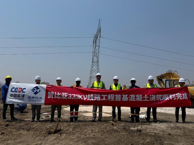
First Foundation Concrete Pour Successfully Completed for Zambia Kafue West–Muzuma 330kV Transmission Line EPC Project
Hot News

评论 (0)