Abstract: In this method, a chain-saw cutter moves laterally to trench, inject grout, and mix and stir the in-situ soil to cast a cement-soil wall. More economical high-strength GZH support pipe piles are selected and inserted into the TRD constant-thickness cement-soil wall, realizing the integration of the support wall and the water-stop wall into one and optimizing construction costs. This paper presents relevant research and application of this technology, and puts forward some conclusions and recommendations.
1. Introduction
With the rapid development of the domestic economy, major cities are undergoing vigorous construction, high-rise buildings are springing up, and the application of deep foundation pits has shown a blowout trend. However, traditional foundation pit support construction techniques can no longer meet the design requirements of super-large-area first-class deep foundation pits in terms of wall-forming depth, uniformity, continuity, surface flatness, thickness, wall stiffness, and water tightness. Therefore, in order to keep pace with the tide of construction projects and break through the bottleneck of deep foundation pit construction, it is urgent to introduce and continuously improve the TRD method.
2. Process characteristics and principles
2.1 High construction precision
Multiple measures such as erecting positioning frames and strictly controlling pile-feeding time are adopted to precisely control the verticality and pile-top elevation of the high-strength GZH support pipe piles fed into the TRD constant-thickness cement-soil wall, ensuring the construction precision of pipe pile feeding.
2.2 Low construction cost
Compared with H-section steel support, row piles + triaxial water-stop support, and diaphragm walls, the use of high-strength GZH support pipe piles can save steel consumption and optimize construction costs.
2.3 Good construction stability
The high-strength GZH support pipe piles are fed 1–2 h after grouting and wall formation, avoiding quality accidents caused by rapid pile sinking. At the same time, the cutter of the pile machine remains below ground throughout the construction process, and there are zero side-tipping or overturning accidents during construction.
2.4 High wall quality
Based on continuous wall construction by the TRD method, the cement-soil is uniformly mixed, and the wall thickness and density are consistent, ensuring high continuity and high water tightness of the wall.
2.5 Strong adaptability
It is suitable for building foundation pit enclosures and water-stop curtains, building foundations and dam foundations, projects affecting the displacement of cut-off works, and anti-sliding of expressway subgrades, covering a wide range of engineering applications. At the same time, it can be constructed in general soil layers such as sand, silty sand, clay, and gravel, and the water-stop depth can enter the soft strongly weathered rock aquiclude, covering a wide range of strata.
2.6 Process principle
(1) In the TRD method, a multi-section box body equipped with cutters on the chain track links is inserted underground. While the cutters rotate and move horizontally and laterally along the foundation, cutting fluid and curing fluid are sprayed from the box body and mixed and stirred with the in-situ soil to form a constant-thickness cement continuous wall. The TRD method forms a continuous wall with few joints, constant wall thickness, and high wall quality.
(2) The high-strength GZH pipe pile is a new type of enclosure pile designed and manufactured to meet the support needs of deep foundation pit projects. Compared with ordinary PHC pipe piles, GZH piles can withstand greater bending moments. Using high-strength GZH pipe piles instead of H-section steel in the TRD constant-thickness cement-soil wall can retain the advantages of high strength and good stability while saving steel and optimizing construction costs.
3. Construction process flow and operation points
3.1 Construction process flow

3.2 Construction operation points
3.2.1 Construction preparation
(1) Level the site and build temporary construction roads. In case of unfavorable geological conditions such as hidden ditches and low-lying areas, measures such as pumping water, clearing silt, backfilling plain soil, and layered compaction shall be taken to ensure that the bearing capacity of the site roads meets the requirements for stable travel of pile machines and lifting machinery.
(2) Following the principle of "from the whole to the part, control first and then detail," starting from the coordinate reference points provided by the client, carry out setting-out positioning and elevation transfer according to the design drawings, and set up permanent or temporary markers.
(3) After setting-out positioning, prepare the measurement technical review sheet and submit it to the supervisor for review, acceptance, and signing. Proceed with mixing construction only after confirmation.
3.2.2 Trench excavation and pile machine positioning
(1) According to the control line of the inner edge of the foundation pit enclosure, use an excavator to excavate the construction trench along the horizontal extension direction of the wall;
(2) Backfill surface soil in the pile machine travel area and repeatedly compact it 5 times with crawler machinery;
(3) Lay steel plates on both sides of the trench and in the pile machine standing area to distribute pressure, thereby ensuring normal construction by the TRD method;
(4) After trench excavation is completed, remove stones, residual soil, and other debris in the trench that affect TRD construction;
(5) Set positioning lines according to pile position information;
(6) Assemble the TRD main machine and cutters at the designated location;
(7) Direct the pile machine to move. Before moving the pile machine, inspect the conditions above, below, left, and right, and remove any obstacles in a timely manner;
(8) After moving, check the positioning deviation of the pile machine, and adjust the levelness and verticality of the pile machine and cutters in a timely manner according to the electronic level and verticality gauges on the pile machine.
3.2.3 Soil cutting, grouting, mixing, and wall formation
(1) Use an excavator to dig a pre-embedded hole 3 m deep, 2 m long, and 1 m wide;
(2) According to the design depth of the cement-soil wall, connect and drive in the cutting boxes in sequence to meet the construction depth requirements. During the self-driving of the cutting boxes, excavation fluid is injected from the front end of the cutting boxes and mixed and stirred with the in-situ soil as the cutting chain rotates;
(3) After excavation reaches the design depth, the cutting box begins lateral excavation to the planned horizontal extension range (usually 5 m);
(4) The cutting box is withdrawn and moved laterally to fully mix and stir the excavation fluid slurry (excavation fluid must be injected during both the advance excavation and the withdrawal lateral movement);
(5) After the cutting box is withdrawn and moved laterally to the cutting box driving position, stop injecting excavation fluid;
(6) Start injecting curing fluid from the front end of the cutting box for curing and wall formation;
(7) After the curing and wall formation range reaches the planned horizontal extension range, stop injecting curing fluid;
(8) Repeat steps (3) to (7) for the next section of soil cutting, grouting, mixing, and wall formation.
During construction, the verticality of the TRD constant-thickness cement wall is monitored throughout by an inclinometer installed in the cutting box. If inclination is found, correct the cutting box in a timely manner with the machine body inclined supports and gantry supports to ensure wall verticality. The inclined supports can adjust the front-back verticality of the machine body, and the gantry can adjust the left-right verticality of the machine body. By repeatedly adjusting the inclined supports and gantry, the wall verticality is controlled within 1/250.
In addition, the excavation fluid and curing fluid shall be strictly controlled and prepared according to design requirements, and the grouting system shall monitor the injection volume of curing fluid to ensure soil mixing quality and wall strength. During the injection of excavation fluid and curing fluid, the slurry pipelines shall be kept free of blockage. If pipeline blockage is found, stop the pump immediately for treatment. After treatment is completed, start slurry delivery only after the cutter sprays slurry back 50 cm.
3.2.4 Standing for 1–2 h and erecting positioning frames
(1) After the TRD constant-thickness cement-soil wall is formed, let it stand for 1–2 h;
(2) Move the positioning steel frame to the top of the cement-soil wall, spanning above the trench, and fine-tune the position of the positioning steel frame until the calibration lines on both sides are flush with the edges of the cement-soil wall. The reserved positioning holes of the fixed steel frame are spaced at 40 cm, ensuring that the pile center spacing after pile insertion is 1200 mm, meeting the requirements of the design drawings;
(3) Considering that the pipe pile wall may rub against the positioning frame during pile insertion and cause position deviation, soil nails are used on site to fix the positioning steel frame to the ground outside the trench.
3.2.5 Pipe pile lifting
(1) Use the three-point lifting method to slowly lift the high-strength GZH pipe pile;
(2) Lower the small hook and slowly lift with the large hook until the pile body is fully lifted into a vertical state;
(3) Move and rotate the crawler crane to move the high-strength GZH pipe pile above the pile position. During pipe pile lifting, a safety warning line shall be set, and no one shall stand within the safety line to ensure safe construction.
3.2.6 Starting pile feeding and verticality control
(1) Fine-tune the pile body position until it aligns with the reserved positioning hole in the positioning steel frame;
(2) Slowly lower the large hook of the crane, and the end of the high-strength GZH pipe pile contacts and passes through the reserved positioning hole in the positioning steel frame;
(3) Observe the contact between the pipe pile end and the reserved positioning hole. If the pile body collides with the positioning steel frame, adjust the pile body position in a timely manner and recheck the pipe pile end for damage;
(4) Repeat steps (2) and (3) until the pipe pile end enters the reserved positioning hole vertically and without collision;
(5) Continue to slowly lower the large hook of the crane, and the pipe pile end passes through the positioning steel frame and enters the TRD constant-thickness cement-soil wall;
(6) Use a theodolite to monitor pile verticality in real time. If the verticality deviation is less than the limit in the early stage of pile sinking, continue to slowly sink the pipe pile; if the verticality deviation exceeds the limit, pull the pile and redo the construction.
Because the verticality deviation of the high-strength GZH pipe pile body is difficult to correct in the middle and late stages of pile sinking, the initial pile feeding stage is the key stage for precise control of the verticality of high-strength GZH pipe piles fed into the TRD constant-thickness cement-soil wall. Construction personnel are required to operate strictly, monitor in real time, and promptly take the verticality correction measures in steps (4) and (6) to ensure that the end and body of the high-strength GZH pipe pile enter the cement-soil wall vertically and without collision through the reserved positioning holes.
3.2.7 Continuing pile feeding and pile-top elevation control
(1) Continue to lower the large hook of the crane, and the high-strength GZH pipe pile body slowly sinks under its own weight;
(2) One hour after pile sinking begins, position the hammer pile driver;
(3) When the pipe pile can no longer sink under its own weight, remove the large hook of the crane and move the crane away;
(4) Use a level to check the pile top elevation. If the pipe pile top has sunk to the design pile-top elevation, end the sinking of this high-strength GZH pipe pile;
(5) If the pipe pile top has not sunk to the design pile-top elevation, first conduct tentative hammering pile sinking: if the pile body descent rate is greater than 50 cm/blow, appropriately reduce the diesel hammer valve; if the pile body descent rate remains at 30–50 cm/blow, normal hammering pile sinking can proceed;
(6) Continue auxiliary pile sinking at a descent rate of 30–50 cm/blow, and use a level to monitor the pile top elevation in real time. When the pipe pile top sinks to the design pile-top elevation, end pile sinking;
(7) Repeat steps (4) to (6) to complete pipe pile sinking one by one.
Precise control of the pile-top elevation of high-strength GZH pipe piles fed into the TRD constant-thickness cement-soil wall requires three strict controls: strictly control the time interval between TRD constant-thickness cement-soil wall formation and pile sinking; strictly control the intervention time of the vibratory hammer pile driver for auxiliary pile feeding; and strictly control the pile body descent rate during auxiliary pile sinking by the hammer pile driver.
4. Project case

Plot E, Phase I Residential Community Center, Nanjing Strait City
Construction depth: 53 m
Construction linear meters: about 200 m
Wall thickness: 850 mm
GZH pipe pile model: 800 mm × 25 m
5. Summary
Compared with traditional techniques, this method saves costs: short construction period, low cost, multiple uses, small environmental impact, can be used as part of the building itself, good water-stop enclosure effect, saves concrete and steel resources, causes no secondary pollution from underground obstacles, improves construction management level, and promotes the development of foundation pit enclosure construction technology. If walls with the same performance are built by other methods, the thickness is 1.0–1.3 m, and the thickness is difficult to control. With this method, the wall thickness is only 0.8 m and the thickness is uniform and controllable, which can save land, steel, and cement, reduce the workload of removing temporary buried objects and restoring the site, and significantly lower the cost.

Lize City Air Terminal Underground Main Structure Nearing Completion: Maximum Transfer Walk Under 4 Minutes After Operation

Anti-seepage Curtain for Main Lock Pit of CSCEC Port Shenqiu Double-Line Lock Project Completed on Schedule

All Pile Foundations Completed on Quanzhou Baiqi Channel

Hainan Upgrades Housing and Municipal Infrastructure
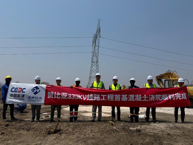
First Foundation Concrete Pour Successfully Completed for Zambia Kafue West–Muzuma 330kV Transmission Line EPC Project
Hot News



评论 (0)