What is the hardest part to draw in foundation pit design? Where is the most difficult part to execute on site? Joints! This article provides a detailed summary of joint details for top-down construction of foundation pits. Come and learn!
Two Walls in One Method
"Two Walls in One" refers to using the retaining wall as a structural wall or part of the structural wall. Rational utilization of the retaining wall reduces costs and reflects green construction.
For integral "Two Walls in One", a composite wall (lining wall) of about 300 mm is set on the inner side of the diaphragm wall, and the two walls block groundwater outside.
For separated "Two Walls in One", pilasters are set at the joints of diaphragm wall panels, and brick or concrete isolation lining walls are set between pilasters. Waterproofing is achieved by "drainage": a drainage ditch is set between the diaphragm wall and the lining wall. If there is leakage, water is drained out through the ditch.

a) With connecting rebar to diaphragm wall b) Without connecting rebar to diaphragm wall
Integral "Two Walls in One" joint

Separated "Two Walls in One" joint
Connection between Diaphragm Wall and Base (Floor) Slab

Connection between diaphragm wall and base slab
1. Joint between Temporary Retaining Wall and Floor Slab in Top-Down Construction of Horizontal Structure
The temporary retaining wall support is replaced by floor slabs, so a reliable support system must be formed between the retaining wall and the horizontal floor slabs to ensure transmission of horizontal forces from the retaining wall. Generally, this is achieved through force-transferring steel sections.

Connection between temporary retaining wall and floor slab
Joint between Steel Lattice Column and Beam-Slab
Two aspects need to be considered: First, before the permanent column is formed, the floor beam (slab) rests on the lattice column, so vertical force transmission at the joint must be considered by setting shear structural rebar, studs, or steel corbels on the lattice column; Second, the steel plates of the lattice column affect the direct continuity of longitudinal beam rebar, so horizontal haunches can be added at the beam joint.

Connection detail between steel lattice column and structural beam-slab

Connection joint between steel column and structural beam

Haunch treatment of beam at joint between steel column and structural beam

Studs and beam haunches at joint between steel column and structural beam

Steel corbels set on steel lattice column
Joint between Concrete-Filled Steel Tube Column and Beam-Slab
The issues to consider are the same as for lattice columns, and the treatment methods are similar: ring-shaped steel corbels, studs + reinforced concrete ring beam joints can be used.

Stud and corbel joint between CFST column and beam > connecting studs

Stud and corbel joint between CFST column and beam > ring steel corbel connection
 Ring beam joint between CFST column and beam

Photo of ring beam joint > ring beam rebar and studs

Photo of ring beam joint > ring beam concrete completed
Joint between Steel Column and Column Pile
In top-down construction projects, the "one column one pile" form of single-pile cap is the most ideal, with simple structure, convenient construction, and good economy. When designed as "one column multiple piles", the pile layout should be adjusted as much as possible so that there is a pile under the column, in order to set a steel column therein, and the bearing capacity of the column pile during construction should be checked. If there is no pile under the column, multiple steel columns and a transfer beam at the column top are needed to transmit loads, which increases resource consumption and construction difficulty, and should be avoided as much as possible.


Steel column and column pile

Connection between CFST column and column pile


Connection between CFST column and column pile

Reserved concrete pouring opening

Pouring column under slab through pouring opening

Construction of column head extending downward for "one column one pile" > formwork with pouring opening

Completed column

Ideal pile layout for multi-pile cap in top-down construction

One column two piles—temporary column underpinning construction
Horizontal Force Transmission at Special Parts
1. Structural post-cast strip: embed steel sections, with studs on the steel sections within the concrete on both sides; a concrete force-transfer plate can also be added under the base slab.
2. Horizontal structure staggered floor: haunch slope ≤ 1/2.
 a) Steel force-transfer strip b) Concrete force-transfer strip
Installation of force-transfer steel sections at post-cast strip

Haunch of structure at floor slab staggered part

Photo of haunch of structure at floor slab staggered part

Change in conventional structural design and construction concept (at soil extraction opening)

Change in conventional structural design and construction concept
Work Instruction for Annular Cutting of Bored Pile Heads
下一篇Mugang Tunnel Achieves Two-Way Breakthrough! Wuyang Expressway Sees New Progress

2024-09-29 13335 0

2024-09-20 13336 0

2024-09-20 13180 0

2024-09-19 12457 0

Lize City Air Terminal Underground Main Structure Nearing Completion: Maximum Transfer Walk Under 4 Minutes After Operation

Anti-seepage Curtain for Main Lock Pit of CSCEC Port Shenqiu Double-Line Lock Project Completed on Schedule

All Pile Foundations Completed on Quanzhou Baiqi Channel

Hainan Upgrades Housing and Municipal Infrastructure
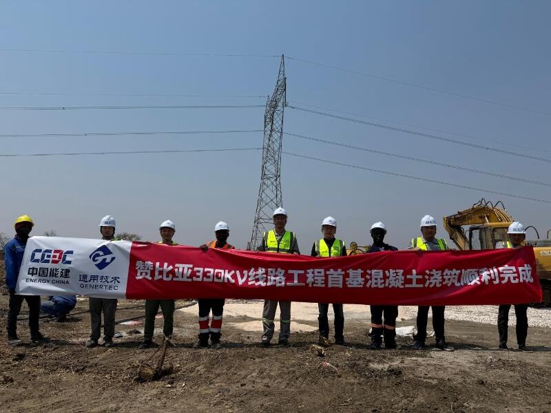
First Foundation Concrete Pour Successfully Completed for Zambia Kafue West–Muzuma 330kV Transmission Line EPC Project
Hot News

评论 (0)