|
1. Layout forms of the main winch mechanism When the main winch mechanism is installed on the mast or luffing mechanism of a rotary drilling rig, it is called a front-mounted main winch mechanism; when installed in the middle of the slewing platform, i.e., near the center of the slewing bearing, it is called a center-mounted main winch mechanism; when installed at the rear of the slewing platform, i.e., behind the engine and in front of the counterweight, it is called a rear-mounted main winch mechanism. (1) Front-mounted main winch mechanism The front-mounted layout is mostly used in small and medium-sized rotary drilling rigs modified from excavator chassis, and is mostly driven by a single hydraulic motor. Due to the space limitation of the mast or luffing mechanism, this type of main winch mechanism mostly adopts a drum with a smaller diameter, and multiple layers of wire rope are wound on the drum. The front-mounted main winch mechanism has the following three advantages: first, there is no need to install the main winch mechanism on the upper slewing platform, so the chassis modification workload is small; second, for rotary drilling rigs using self-made chassis, the layout of the slewing platform is more compact and reasonable, thereby reducing the area of the slewing platform and making the rotary drilling rig more agile and convenient to operate; third, the lifting force of the main winch mechanism only generates positive pressure on the mast, without generating bending moment on the mast, so the force on the mast is more reasonable. The main disadvantage of the front-mounted main winch mechanism is that the drum can only use multi-layer wire rope winding, and the wire rope is prone to jumping, disordered winding, and biting, which shortens the service life of the wire rope. (2) Center-mounted main winch mechanism The center-mounted layout is mostly used in medium and large rotary drilling rigs with dedicated chassis. The drum is mostly single-layer or double-layer wound. It is mostly driven by dual hydraulic motors and dual reducers, and a small number are driven by dual hydraulic motors and a single reducer. The center-mounted main winch mechanism has the following four advantages: first, it can install a drum with a larger diameter and single-layer winding, thereby avoiding the disadvantages of wire rope jumping and disordered winding, and improving the service life of the wire rope; second, the main winch mechanism is close to the center of the slewing bearing, so when the main winch mechanism lifts and lowers, the bending moment applied to the slewing bearing and the main beam of the slewing platform is small; third, the wrap angle of the wire rope on the guide pulley at the back of the mast is small, so the wear of the pulley is small; fourth, the bending moment applied by the lifting force of the main winch mechanism to the mast is small. The disadvantage of the center-mounted main winch mechanism is that it can only use a self-made or custom-made dedicated chassis, the slewing platform area is large, and the installation and maintenance of the main winch mechanism are inconvenient. (3) Rear-mounted main winch mechanism The rear-mounted layout is mostly used in large rotary drilling rigs modified from excavator chassis, mostly using single-layer winding drums, mostly driven by dual hydraulic motors and dual reducers, and a small number using dual hydraulic motors and a single reducer. The rear-mounted main winch mechanism has the following three advantages: first, it can use an excavator chassis without the need to separately design a dedicated chassis; second, it can use a single-layer winding drum to avoid wire rope jumping and disordered winding, thereby improving the service life of the wire rope; third, the main winch mechanism is arranged in front of the counterweight, which is equivalent to adding a part of the counterweight, thereby improving the stability of the rotary drilling rig. The rear-mounted main winch mechanism has four disadvantages: first, compared with the front-mounted main winch mechanism, the rear-mounted main winch mechanism requires a larger modification workload on the excavator chassis; second, the wrap angle of the wire rope on the guide pulley at the back of the mast is large, so the wear between the wire rope and the pulley is large, and the service life of the wire rope is shorter. Third, when the wire rope passes over the back pulley to lift and lower, the bending moment borne by the mast is large. Fourth, the rear-mounted main winch mechanism generates a large overturning moment on the slewing bearing and a large alternating load on the main beam of the slewing platform, which easily causes fatigue damage to the main beam of the slewing platform. 2. Drive forms of the main winch mechanism The drive forms of the main winch mechanism of a rotary drilling rig are divided into two types, namely single-reducer drive and dual-reducer drive. (1) Single-reducer drive The main winch mechanism driven by a single reducer is mainly composed of reducer 1, bolts (2, 4), frame 3, drum 5, and spherical roller bearing 6, as shown in Figure 1. Reducer 1 is rigidly connected to the right end of the main winch frame 3 through bolt 2. Reducer 1 plays the role of reducing speed and supporting the right end of drum 5. Reducer 1 drives the drum to rotate, and its output end is connected to drum 5 through bolt 4. The spherical roller bearing 6 at the left end of frame 3 supports the left end of drum 5. This bearing not only has a large load-bearing capacity but also has an automatic self-aligning function, which can appropriately adjust the deformation of drum 5 caused by force.  When using a single-reducer drive, either a single hydraulic motor can be selected to drive the reducer, or dual hydraulic motors can be selected to drive the reducer. (2) Dual-reducer drive The dual-reducer drive is mostly used in large rotary drilling rigs. When the drum lifting force generated by the output torque of a single reducer is insufficient, a dual-reducer drive can be used. The main winch mechanism driven by dual reducers is mainly composed of reducers (1, 10), bolts (2, 4, 8, 9), frame 3, drum 5, outer transition disc 6, inner transition disc 7, and pin shafts 11, as shown in Figure 2.  The right end of this main winch mechanism is the same as the right end of the single-reducer drive main winch mechanism, and drum 5 is rigidly connected to frame 3. The left end of frame 3 is provided with an outer transition disc 6 and an inner transition disc 7. The outer transition disc 6 is fixed to frame 3 through bolt 8, and the inner transition disc 7 is fixed to reducer 10 through bolt 9. Four pin shafts 11 are provided on the mating surface between the outer transition disc 6 and the inner transition disc along the circumferential direction (both ends of the pin shafts are provided with baffles to prevent the pin shafts from slipping out), which are used for circumferential positioning of the outer transition disc 6 and the inner transition disc 7. When reducer 10 outputs torque to drum 5, the reaction force of reducer 10 acts on frame 3 through the inner transition disc 7, pin shafts 11, and outer transition disc 6. This floating transition disc structure can not only play a flexible supporting role but also transmit the reaction torque of the reducer. By utilizing the degree-of-freedom characteristics of pin shaft fixation, it can ensure the connection between the reducer and the frame and also improve the service life of the reducer. |
Methods for Saving Fuel in Rotary Drilling Rigs
下一篇China to Build 480-km Railway Linking Six East African Countries

2024-09-29 13335 0

2024-09-20 13336 0

2024-09-20 13180 0

2024-09-19 12457 0

Lize City Air Terminal Underground Main Structure Nearing Completion: Maximum Transfer Walk Under 4 Minutes After Operation

Anti-seepage Curtain for Main Lock Pit of CSCEC Port Shenqiu Double-Line Lock Project Completed on Schedule

All Pile Foundations Completed on Quanzhou Baiqi Channel

Hainan Upgrades Housing and Municipal Infrastructure
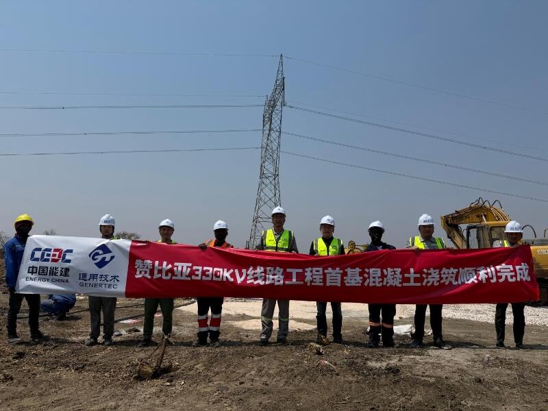
First Foundation Concrete Pour Successfully Completed for Zambia Kafue West–Muzuma 330kV Transmission Line EPC Project
Hot News

评论 (0)