II. Characteristics of the 1550 Cast-Rolling Mill Foundation
(1) Complex section forms. The elevation differences of the 1550 cast-rolling mill foundation are large, with undulations and irregularities, and the equipment load distribution is uneven, resulting in complex overall forces on the foundation and relatively many section forms. The detailed dimensions of the foundation can only be reflected through multiple sections.
(2) Many bolt holes and non-uniform. The 1550 cast-rolling mill is a precision equipment, which requires good fixation and a solid equipment foundation to smoothly transfer loads to the foundation soil. Anchor bolts are the link between the equipment and the foundation. The reserved bolt holes in the 1550 cast-rolling mill foundation total 101, including 56 with a diameter of 100mm, 17 with a diameter of 150mm, 6 with a diameter of 160mm, and 22 with a diameter of 200mm, and the elevations and lengths are all different, which increases the design difficulty.
(3) Many embedded parts, easy to miss items. All cable trench and hydraulic trench side walls of the 1550 cast-rolling mill are provided with embedded parts at a spacing of 1200mm, and steel trench beams are set at all trench corners. There are also nearly 40 embedded parts that must be reserved according to process requirements. Because these embedded parts have different functions, their sizes are different, the number of anchor bars varies, and the lengths of anchor bars are different. These must be calculated according to the tensile force, compressive force or shear force they bear, which increases the complexity of the foundation design. III. Technical Requirements for the Foundation Design of the 1550 Cast-Rolling Mill The foundation design of the 1550 cast-rolling mill should ensure that the foundation has strong stability and deformation resistance. According to the data provided by Zhuoshen Company, the technical requirements for the 1550 cast-rolling mill foundation are: (1) Maximum rolling torque of a single roll of the main machine is 20Tm; (2) Maximum tension torque of coiling is 10Tm; (3) Moving load: 20T at the roll changing track; (4) 10T at the coil car track. IV. Difficulties and Solutions in the Foundation Design of the 1550 Cast-Rolling Mill
(1) Collect technical data, understand geological conditions, and fully do the preliminary design work. In the early stage of the 1550 cast-rolling mill foundation design, Zhuoshen Company provided relevant machine data (civil construction condition drawings). These data mainly include: technical performance related to the machine (name, model, transmission mode, power and load conditions); the outer contour drawing of the machine base and the positions of pits, holes, trenches, and anchor bolts set in the foundation as required. Before design, conduct a detailed analysis of the geological conditions of the foundation, obtain correct geological data, and adopt reasonable structural design to ensure the stability of the foundation, thereby achieving the purpose of safe operation.
(2) Determine the embedment depth and dimensions of the foundation. 1. Determine the embedment depth. Under the premise of meeting process requirements, according to the embedment depth of the workshop foundation and pipe trenches, the depth of bolt holes, and considering saving engineering costs, the embedment depth of the 1550 cast-rolling mill foundation changes continuously with requirements. The connection between two soil layers at different elevations is achieved by sloping. It should be noted that sloping is not easy to handle at the intersection of cross sections and longitudinal sections, because what is cut is a certain elevation on the slope, which cannot fully reflect the section form of the foundation. In section treatment, the slope positions should be staggered as much as possible. 2. Determine the foundation dimensions. According to the strong integrity of the 1550 cast-rolling mill foundation, the foundation is designed as a solid foundation. Considering reducing the dead weight of the foundation and saving building materials, the external dimensions of the foundation are determined according to the civil construction condition drawings provided by Zhuoshen Company, while meeting the structural requirements for the overall stiffness of the foundation and the so-called "centering" requirement (i.e., the total center of gravity of the machine foundation and the center of the foundation base should be on the same vertical line as much as possible); at the same time, it meets the dimensions required for installation, adjustment and maintenance. The determined external dimensions of the foundation are: 16240mm, 12540mm, 17570mm, 12540mm.
(3) Check the bearing capacity of the foundation soil. Because the shear strength of the foundation soil decreases under dynamic load and additional settlement occurs, the design value of the bearing capacity of the foundation soil should be reduced. Thus, the foundation design of the 1550 cast-rolling mill should satisfy: P≤afp - design value of average static pressure at the bottom of the foundation, kpa; f - design value of bearing capacity of the foundation soil determined according to the Code for Design of Building Foundations, kpa; a - dynamic reduction coefficient. For machine foundations with small vibration acceleration, generally a=1.0 can be taken.
(4) Carry out reinforcement calculation. 1. Foundation reinforcement and selection of concrete
1. To avoid uneven settlement of the equipment foundation, according to Clause 10.0.7.1 of the Code for Design of Dynamic Machine Foundations: "For foundations with a length greater than 6m and less than 11m, the top and bottom surfaces; the edges of pits, trenches, and openings in the foundation or parts where the foundation section changes sharply; parts with few support points and large concentrated forces where the foundation is subjected to uneven forces or local impact forces; reinforcement mesh with a diameter of 8~14mm and a spacing of 150~250mm should be provided." Strengthen the top slab and bottom slab structures of the 1550 cast-rolling mill foundation. Double-layer bidirectional reinforcement is provided in the foundation to strengthen the integrity, stability and deformation resistance of the foundation structure, ensure that the equipment foundation does not lose stability, and also prevent uneven settlement of the equipment foundation caused by eccentric loads.
2. The anchorage and connection of reinforcement are key considerations in the design. According to the Code for Design of Concrete Structures GB50010-2002, when the tensile strength of reinforcement is fully utilized in the calculation, the anchorage length of tensile reinforcement should be calculated according to the specified formula: for ordinary reinforcement Lα=αfy/ftd, where Lα is the anchorage length of tensile reinforcement; fy is the design value of tensile strength of ordinary reinforcement; ft is the design value of axial tensile strength of concrete; d is the nominal diameter of reinforcement; α is the shape coefficient of reinforcement. The lap length of the tied lap splice of longitudinal tensile reinforcement should be calculated according to the following formula based on the percentage of the lap splice area of reinforcement in the same connection section: Ll=§la, where Ll is the lap length of longitudinal tensile reinforcement; la is the anchorage length of longitudinal tensile reinforcement; § is the correction coefficient of lap length of longitudinal tensile reinforcement; in any case, the lap length of the tied lap splice of longitudinal tensile reinforcement should not be less than 300mm. 3. According to the basic requirements for the durability of structural concrete in the Code for Design of Concrete Structures GB50010-2002, "the environmental category is Class I (normal indoor environment), the minimum concrete strength grade of the foundation is C20. Considering the tight construction schedule and relatively shortened time, it is required to increase the concrete strength as early as possible. An early strength agent is added when pouring concrete, and the concrete grade of the foundation is increased to C25. The secondary grouting layer uses C30 fine stone concrete.
2. Reservation of anchor bolt holes. The precise positioning of bolt holes is crucial; any slight error may cause the entire foundation to be scrapped. Except for rectangular bolt holes, other bolt holes use spiral corrugated pipes, which are directly poured into the concrete. After construction, the spiral corrugated pipes become integrated with the concrete and do not need to be removed, making construction simple and significantly improving the force effect. Verified by construction and trial operation, the foundation design of this 1550 cast-rolling mill fully meets production requirements and has achieved satisfactory results.
V. Matters Needing Attention in Equipment Foundation Design
(1) Under the premise of meeting the requirements for foundation stability and deformation, the foundation should be buried as shallowly as possible. When the bearing capacity of the upper foundation soil is greater than that of the lower layer, the upper layer should be used as the bearing layer;
(2) The reserved bolt holes and embedded parts of the foundation must be accurate. The designer should check multiple times to ensure no mistakes.
VI. Conclusion The equipment foundation is one of the important guarantees for the normal operation of equipment. The stability of the foundation is very important. Calculations of bearing capacity, deformation and stability should be carried out, and a reasonable, economical and safe equipment foundation should be formulated according to actual geological conditions.
Technology and Application of Roof Bolt Support for Gob-Side Entry Retention
下一篇Application of Impact Compaction Technology in Treating Poor Subgrade Original Ground

2024-09-29 13335 0

2024-09-20 13336 0

2024-09-20 13180 0

2024-09-19 12457 0

Lize City Air Terminal Underground Main Structure Nearing Completion: Maximum Transfer Walk Under 4 Minutes After Operation

Anti-seepage Curtain for Main Lock Pit of CSCEC Port Shenqiu Double-Line Lock Project Completed on Schedule

All Pile Foundations Completed on Quanzhou Baiqi Channel

Hainan Upgrades Housing and Municipal Infrastructure
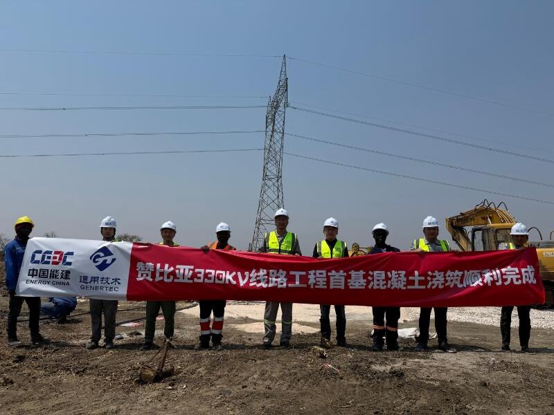
First Foundation Concrete Pour Successfully Completed for Zambia Kafue West–Muzuma 330kV Transmission Line EPC Project
Hot News

评论 (0)